Geometry, placement and deployables
Read placement and deployable decisions
Open Spacecraft > Placement for the Symmetric deployable arrays starter. Read the physical disposition before moving to exposure, deployment and CAD.
Check the stowed fit
Compare Packaging volume and Component disposition in Stowed fit. Volume is one screening quantity; the placed/unplaced states retain the outcome of the actual layout checks. Use Inspect stowed CAD to examine that layout.
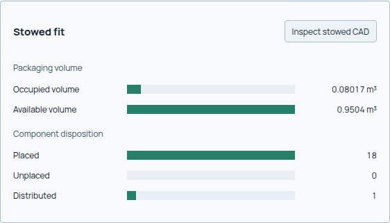
This study records 18 placed items, 0 unplaced and 1 distributed contribution. Occupied volume is 0.08017 m³ within 0.9504 m³ available. The overall placement state still carries a warning, which should remain part of the review.
Inspect exposure and a mounted component
Select downlink / deployed under Exposure scenarios. Read Earth, ram and Sun exposed areas separately. In Selected hardware & mounting, select a component to inspect its face, dimensions and shape basis, then use Inspect in CAD to locate it.
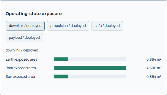
For this state the recorded ram-exposed area is 4.506 m², while Earth and Sun exposure are each 0.864 m². These directional quantities are not interchangeable with total panel or surface area.
Reconcile panel area and deployment clearance
Open Deployables. Compare Required active area, Realized active area and Gross panel area in Power area contract, then read Endpoints & deployment path. Inspect deployed in CAD, Inspect stowed in CAD and Inspect sample in CAD lead to the corresponding represented geometry.
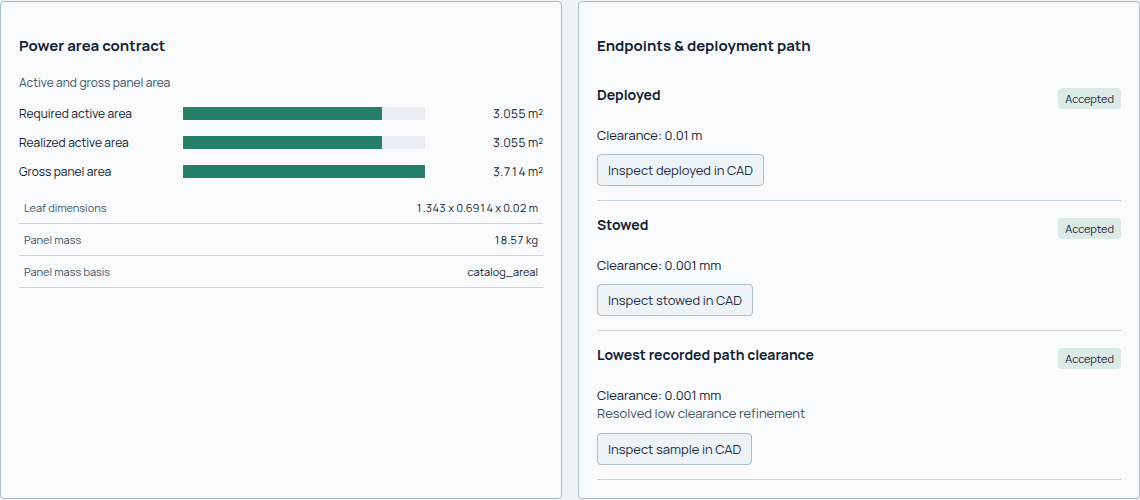
The selected accordion design records 3.055 m² active area and 3.714 m² gross panel area. The lowest recorded path clearance is very small: read its numerical basis and the represented geometry before carrying it into mechanical design.
Understand the selection among recorded concepts
Continue to Recorded concepts. Expand Why selected for the selected design and Decision reason for an alternative, then Search scope. This explains the decision from the retained candidates rather than from visual similarity alone.
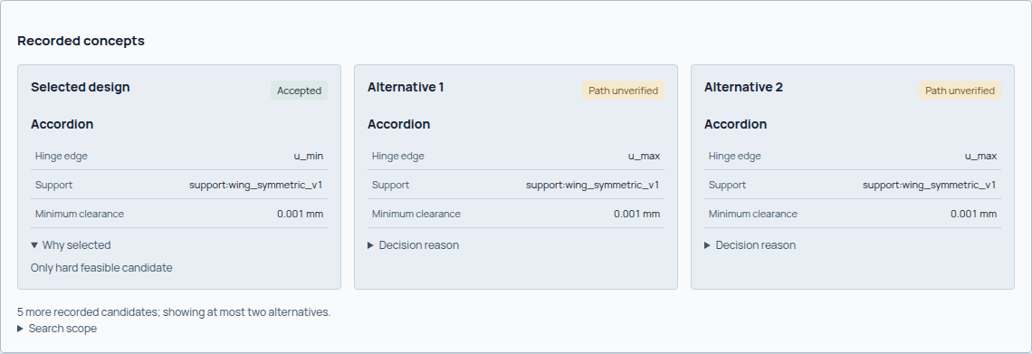
The selected concept is Accepted; the two displayed alternatives are Path unverified. Five further candidates are recorded but not shown in this compact view. A selected candidate is not proof that every possible mechanism was searched.
From hardware demand to a physical layout
Topology provides the structural layout; placement assigns equipment to it. The launch envelope constrains accommodation; it does not directly prescribe all bus dimensions. Hardware bounds, keep-outs, permitted faces, symmetry rules and search policies limit what can be placed.
Face area alone does not establish panel fit. Each allowed aspect ratio must fit
the available in-plane dimensions under the face-support rule. The panel area
used by placement comes from that run's coupled sizing state; it need not equal
the final area of a previous run. Inspect result.placement records and
diagnostics.rejected_candidates to separate face-fit rejection, collisions and
keep-outs. More lookahead cannot make an oversized rectangle fit a face. A failed
power closure may retain a bounded area for diagnosis; that value is not proof
of a feasible array. See power coupling.
Record the selected topology, placement status, unplaced items, body frame and geometry fidelity. A completed placement search may still leave warnings or unplaced hardware. Use the preview to inspect that represented layout; detailed manufacturing features require their own model.
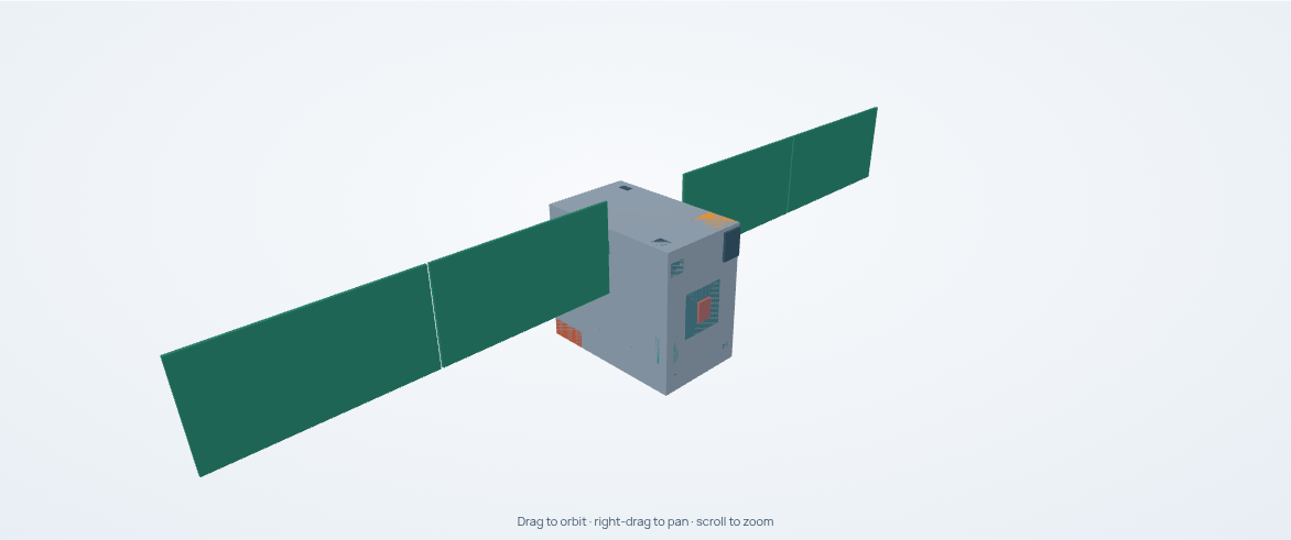
Actual CAD output from the Symmetric deployable arrays starter. The assembly represents the study's concept geometry. Open the worked visual walkthrough to compare the stowed state and inspect the interior.
Configuration and deployment
Deployable families/mechanisms define rigid links, joints, reachable states and transitions. Launch uses a stowed state; operational modes bind to their specified states. Partial states must be authored explicitly. Review missing-state policy and any default/warning rather than assuming every mode uses the fully deployed configuration.
Geometric path verification samples synchronized transitions with bounded refinement and collision checks. Read the evaluation budget, sampled clearance, termination reason and approximation records. Sampled geometric clearance is not continuous-time dynamics, deployment reliability, hinge-load qualification or proof against all unmodeled collisions.
Fixed-panel studies may have no deployables result. Do not manufacture one from a geometry preview. When an articulated assembly exists, its state-dependent mass properties and exposed surfaces feed other models.
Directional loading
All surface vertices, normals, centers, CGs and lever arms use body XYZ. A source vector points from the spacecraft toward the source; the ram vector points upstream into incoming flow. For a one-sided planar patch:
\(\widehat{\mathbf n}\) is the outward unit normal and \(\widehat{\mathbf s}\) the unit vector toward the source. \(\mathbf r_{\mathrm{visible}}\) is the center of visible projected area; \(\boldsymbol\ell\) is its lever arm about the state CG.
Areas are in m² and positions/lever arms in m. Two-sided patches use the absolute dot product. Zero exposure is a valid zero area with a null center and lever arm; it does not imply an unknown nonzero load.
Deterministic planar overlap accounts for opaque nearer polygons occluding the union of farther projections. Surface rows retain owner, state, functional role, method and approximation IDs. Aggregate areas can be recomputed from these rows.
The inventory is bounded to 128 planar patches and 32 scenarios. Each scenario binds an operating mode, geometry state and environment case, with sun, Earth and/or ram sources. Explicit state-resolved surfaces take precedence over primitive/equivalent areas and the degraded analytic six-face fallback. Internal placement boxes are not external loading surfaces.
Coupling and interpretation
flowchart TD
    accTitle: Geometry information used by the subsystem models
    accDescr: State-specific surfaces and source directions yield visible projected areas and application points. Power and thermal use exposure, while propulsion and attitude control also use application points and CG lever arms. Each consumer applies its own physical coefficients.
    SURFACE["Surfaces in the selected geometry state"] --> PROJECTION["Projection and occlusion"]
    DIRECTION["Sun, Earth and ram directions"] --> PROJECTION
    PROJECTION --> AREA["Visible areas and application points"]
    AREA --> ENERGY["Power and thermal: exposure"]
    AREA --> FORCE["Propulsion and ADCS: area and lever arm"]
    CG["State center of gravity"] --> FORCE
The shared geometry calculation ends at areas, application points and lever arms. The receiving model then converts them into generation, heat, force or torque using its own physical assumptions.
| Consumer | Uses geometry for | Calculates separately |
|---|---|---|
| Power | Visible sun-facing solar-generation area | Flux, efficiency, degradation, availability and energy balance |
| Thermal | Source exposures and surface identities | Absorbed heat, radiation, conduction and temperature |
| Propulsion | Ram area and application point | Drag force, maneuver demand and propellant |
| ADCS | Area, application point and CG lever arm | Disturbance torques and actuator/control needs |
Do not multiply eclipse, flux, duration, optical properties or margins into the geometric area. Those belong to their consumers. Repeating a cosine projection there would double-count incidence.
Authority and limits
Applicability may be applicable, degraded or unsupported. Curved/mesh-only
visibility, transparent surfaces, multiple reflections, excessive scenario or
patch counts, and missing required state/attitude information do not receive
silent substitutes. Detailed mesh ray tracing and deployment dynamics require
specialist treatment.
Use EX04 to examine topology consequences and EX05 to distinguish a scalar mass budget from resolved spatial properties. Exact interfaces: placement, deployable assembly, and geometry loading.
Bus dimensions and design iteration
For a selected rectangular topology, shell_params.x_m, y_m and z_m set the
bus dimensions used by placement. Cylindrical templates use twice radius_m and
height_m. These values come from the topology definition; launcher envelope
limits constrain accommodation and do not resize that topology. A different
architecture preset can retain the same bus and identical ADCS components.
Inspect the actual catalog definitions, not just their names.
Automatic topology selection ranks placement candidates by hard failures, margin penalties and placement objective score. It does not optimize the A9 numeric assessment. Lookahead is a repair path when ordinary placement cannot place a component; increasing its depth need not change an already feasible layout. Broadening face or shape choices can also return the same design.
When improving packaging, connect the recorded utilization and score cap to the selected topology, component volumes, mounting constraints and feasible alternatives. Keep requirements fixed, state the proposed causal change, and compare actual physical results after the run. A new input snapshot alone is not evidence of improvement.
The sidebar and Configure can author spacecraft.geometry through the normal
validated proposal and Apply and run flow:
busbinds to the selected fixed rectangulartopology_id, with positive finitex_m,y_m,z_min metres. Normalized mounts follow the resized shell. Absolute keepouts retain their dimensions and must remain inside it.fixed_panelsbinds each shape to the selectedarchitecture_profile_idand exactcomponent_idof an explicitfixed_solar_panelarchitecture node usingfixed_solar_area. Read these node IDs fromread_design_catalog. Each entry supplies orderedaspect_ratio_candidates(width/height). One to sixteen distinct ratios from 0.000001 to 1000000 are supported per panel, with at most sixteen named panels. These numerical bounds do not establish engineering feasibility.
EPS still determines required panel area; the existing allocation fraction,
thickness, mass rules and face/collision checks remain authoritative. Editing
ratios does not request a different area or relax fit. Each ratio changes the
rectangle tested at the current coupled sizing area. Shapes require the
fixed_panels power subsystem. Changing topology or architecture requires
rebinding or clearing the corresponding project geometry; stale bindings fail
canonical validation. Removing an override restores the catalog definition.
These are project inputs, captured in the run snapshot and applied to private
copies of the base definitions. Catalog properties remain the shared base;
project_properties show current authored geometry when it differs. Neither
proves a previous run used those values: inspect its snapshot and retained
placement records. Arbitrary topology construction and edits to shared catalog
files remain outside this authoring surface.