EX04: topology and launch mounting trade
All examples and learning routes
Compare the same mission and selected hardware in two physical layouts. This CLI pair reproduces EX10 · Flat deck and EX11 · Spine. Both should complete placement, CAD fidelity and numeric evaluation, while retaining the documented warnings.
What changes
| Choice | Flat deck | Spine |
|---|---|---|
| Topology | starter_flat_v1 |
starter_spine_v1 |
| Bus X × Y × Z | 2.0 × 0.8 × 1.2 m | 1.2 × 0.8 × 2.0 m |
| Launch orientation | xyz: body X along launcher U |
yzx: body Z along launcher U |
| Launch accommodation | Same Miura 5 large-interface reference fairing | Same reference fairing |
The launch orientation changes with the topology so each long bus axis lies along the launch axis. Mission, hardware selections, operations, interface and fairing requirements stay fixed. This compares two packaged configurations; it does not isolate topology independently of mounting orientation.
The prior spine setup used a near-limit radial arrangement. The revised orientation has about 0.69 m of modeled radial diameter margin in the qualification run. This is an envelope-screening quantity, not a measured installation gap or a tolerance analysis. Inspect the current run's launch checks when changing inputs.
Run both variants
Download EX04, extract it and run from EX04:
sindri validate-project flat-deck/study.yaml
sindri run flat-deck/study.yaml --output-root runs/flat-deck
sindri validate-project spine/study.yaml
sindri run spine/study.yaml --output-root runs/spine
Open both completed bundles in the Console. Use Compare with and verify the input diff before comparing results. Only the two topology-selector leaves and two launch-orientation leaves differ; the archive checks that controlled set.
Inspect the comparison
Compare Placement and Spacecraft first, with the outer bus hidden to reveal decks, cutouts and equipment. Then read Mass, Thermal, Power, ADCS and Launch. Repositioning hardware changes geometry-dependent loading, inertia, heater demand and coupled budgets. Lower mass or a higher score is not a general proof that one topology is superior.
Verified results
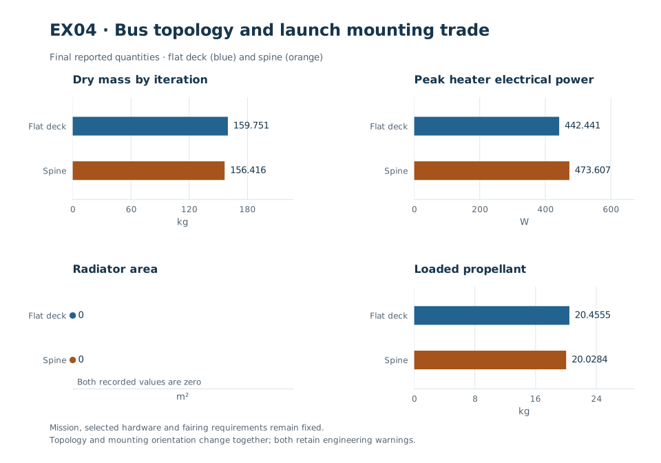
The pair changes topology and the launch mounting orientation needed to align each long bus axis with launcher U. Mission, hardware choices and fairing requirements remain identical. Each chart compares the same final quantity and unit.
The following values are generated from the verified observations. Read the assessment states before treating any reported quantity as a usable design budget.
flat-deck — run lifecycle: completed.
| Quantity | Observed value | Unit |
|---|---|---|
| Nominal dry mass | 159.751 | kg |
| Required solar array area | 2.92045 | m² |
| Realized solar array area | 3 | m² |
| Minimum state of energy | 185.15 | Wh |
| Peak heater electrical power | 442.441 | W |
| Radiator area | 0 | m² |
| Loaded propellant | 20.4555 | kg |
| Total delta-v | 255 | m/s |
| Communications hardware mass | 4.85 | kg |
| Battery capacity | 900 | Wh |
| Reported cost estimate (base) | 8.3139e+06 | USD (2025) |
spine — run lifecycle: completed.
| Quantity | Observed value | Unit |
|---|---|---|
| Nominal dry mass | 156.416 | kg |
| Required solar array area | 3.2436 | m² |
| Realized solar array area | 3.25 | m² |
| Minimum state of energy | 138.911 | Wh |
| Peak heater electrical power | 473.607 | W |
| Radiator area | 0 | m² |
| Loaded propellant | 20.0284 | kg |
| Total delta-v | 255 | m/s |
| Communications hardware mass | 4.85 | kg |
| Battery capacity | 900 | Wh |
| Reported cost estimate (base) | 8.43514e+06 | USD (2025) |
Full result states, diagnostics and provenance.
These are conceptual layouts with complete evidence under their authored cases. They retain reference-model and operating-envelope limits. The template called “spine” uses recorded internal deck regions; its name does not establish a detailed central load-bearing spine or structural qualification.