Mass budgets and mass properties
Inspect a mass budget in the Console
Open a completed run and choose Sizing and budgets > Mass. The captures below use the Symmetric deployable arrays starter. Begin with the budget boundary, then follow its largest contribution into hardware.
Compare the cases and read the build-up
Select Nominal under Mass cases. Read Mass breakdown beside Design range, then the Inside the selected budget table. Switch between Low, Nominal and High to see the structure/harness assumptions; the ? beside Mass cases explains what changes. Use kg for absolute contributions and % for their dry-budget shares when those shares are assessed.
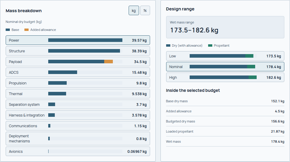
The nominal case reports 156.6 kg dry and 178.4 kg wet. The wet range is 173.5–182.6 kg across these assumptions. The overall mass assessment is Not assessed because no matched nominal mass limit is recorded; the range does not supply that missing requirement.
Follow a contribution to its owner
Select Power in the breakdown. Selected contribution separates its base mass, allowance and budget share; Associated hardware identifies the array, battery and power distribution that support it. Open Contribution source for the accounting basis, or Inspect hardware for the captured component.
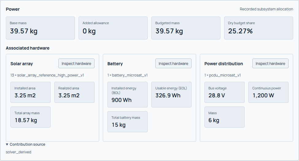
Power contributes 39.57 kg here. The hardware cards explain where it comes from; they are supporting detail for that contribution, not extra masses to add again.
Inspect the spatial mass basis
Open Mass properties and analysis context. Read the center of mass and inertia with their configuration and frame before carrying them into launch or ADCS calculations. An unavailable spatial quantity must remain unavailable.
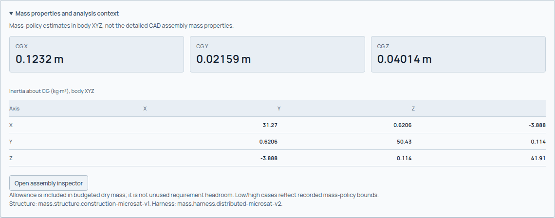
These are mass-policy estimates in body XYZ. The inertia table names its reference point and axes; preserve that basis when comparing it with a launch-frame or actuator calculation. Open assembly inspector leads to the separate represented assembly.
Build a budget without counting an item twice
The budget combines payload, subsystem hardware, launch separation, deployable mechanisms, structure and harness/integration. Track each contribution in kg and identify the result that supplies it. If propulsion already includes a tank, adding that tank again as a separate component overstates the budget. Apply the same ownership check to margins.
Each budget bucket retains raw mass, applied margin factor, margin added, final mass and provenance. The basic accounting is:
The index \(i\) identifies a budget bucket; \(f_{i,\mathrm{margin}}\) is its dimensionless applied margin factor.
Read the actual bucket boundaries and selected state. A spacecraft-only mass, a wet mass and a mass including an adapter cannot be compared as if they were the same quantity. Separation hardware is already represented in the launch state's mass accounting; do not add it again.
Operational and depleted propulsion states
The budget's dry/wet cases and the spatial stowed/deployed configurations are
different from propulsion's depletion states. Read result.propulsion
/payload/mass/mass_states alongside /payload/mass/depletion_steps for the
recorded BOL, operational, pre-disposal and EOL masses.
In the propulsion mass result, propulsion-mass.operational is the end mass of
the first allocation, orbit raising. It retains dry spacecraft and propulsion
hardware, remaining usable propellant, reserve and residual propellant. BOL is
the first allocation's start mass, pre-disposal is the collision-avoidance end
mass, and EOL is the disposal end mass. These states do not automatically remove
separation hardware or imply a mechanical deployment. See
propulsion for the sequential rocket-equation boundary.
Read each consumer's mass basis and check separately. Launch separation hardware has minimum/maximum spacecraft-mass accommodation bounds; the launch-vehicle profile's maximum-wet-mass check is separate. An unsupported vehicle limit does not imply that no separation-system mass check exists. Preserve the values and case/state identities recorded by each consumer rather than substituting a budget value or a coupled convergence-state value.
Hardware ownership and completeness
Selected ADCS hardware and fixed-array panels use their owning solver's mass, not a fraction of the subsystem budget or a placement minimum. Repeated devices share that inventory by count; panel allocations share the EPS gross area and mass. Deployment roots are geometric attachment references: their physical mass belongs to the articulated mechanism, not a second percentage of power mass.
Known but unplaced items remain individually recorded. Diagnostic mass properties
may represent an unsited item as a provisional centered bus box; mass_coverage
remains incomplete and these properties are not an accepted design basis. Wheel
clusters use a conservative enclosing package based on the selected wheel size,
not a detailed mechanical layout. Unrelated subsystem spatial approximations
remain in scope as conceptual estimates.
Bounded structure and harness policies
The maintained policy families have low, nominal and high parameter cases. Automatic selection requires exactly one applicable structure policy and one harness policy for the input class. Explicit selection requires both known, applicable IDs. Unknown or ambiguous selections fail rather than silently choosing a substitute.
New default structure policies sum gross outer-panel and deck areas times areal mass, frame-member lengths times linear mass, and explicit per-interface attachment allowances. Each term records its dimensions, position, coefficient, mass and sources. There is no volume penalty in this construction path. Harness retains its bounded base, subsystem, area and interface contributions.
Compact solid-panel assumptions use 5052-H32 aluminium at 2680 kg/m3 and 1.0/1.27/1.5 mm thickness. The nominal wall-only comparison uses the Pumpkin solid-wall family. The folded walls are not also counted as separate frame material. Larger panel and frame assumptions use the commercial Plascore AA3.6-80 panel table and Aalco 25 x 25 x 3 mm angle, at 0.38 kg/m. These are component mass references, not whole-spacecraft or flight-qualified structural models. Low/high construction choices are engineering bounds, not manufacturing tolerances.
The supported rectangular topologies are rect_xz_decks_v1, rect_array_roots_v1,
flat_single_deck_v1 and flat_dual_deck_v1. Internal mount regions are treated
as gross conceptual decks; cutouts, edge closures and detailed joints are not
resolved. Solid-panel use is limited to 0.09-0.34 m bus edges. Sandwich panels
use 0.1-2.4384 m edges, with no panel's shorter edge exceeding 1.2192 m stock
width. These are declared use bounds, not validated spans. The 10/20/30 g
per payload/deployable interface attachment allowance excludes separately owned
deployment mechanisms; its spatial allocation is approximate.
Outside those bounds, structural mass is unresolved and the budget is a known
subtotal. It does not silently use a different equation. Original volume-based
*-v2 structure policies remain available by explicit ID for reproducibility;
the default catalog is mass.reference-policies-v3. No structural load or
modal-frequency qualification is implied by the new mass build-up.
Only nominal enters the multidisciplinary iteration. Low/high are aligned bounded side cases; they are neither statistical confidence intervals nor an independent Cartesian sweep of every uncertain parameter.
Explore the coupled examples
Run configs/examples/adcs_mass_fixed/study.yaml for a 5 kg instrument with
body-mounted panels and three orthogonal wheels, or
configs/examples/adcs_mass_deployable/study.yaml for a 30 kg instrument with
articulated arrays and a four-wheel, one-wheel-out layout. Both use a
1.2 x 0.72 x 1.1 m conceptual bus, three magnetorquers and explicit sensor roles.
The second topology adds array-root mounts; it is not a new structural analysis.
These are ADCS/mass qualification examples, not complete reference spacecraft. They use an explicit 75 degree beta design point, not all-season solar coverage. The fixed-array case closes its represented power cycle. The deployable case demonstrates mass/area ownership and changing inertia but retains a failed power balance for its resolved orientation. Inspect that failure rather than reading complete mass coverage as overall design approval. Catalog archetypes, source span bounds and native ADCS disturbance assumptions remain screening-level.
python -m sindri run configs/examples/adcs_mass_fixed/study.yaml
python -m sindri run configs/examples/adcs_mass_deployable/study.yaml
In Console, compare the Mass cases and their construction assumptions, then the
Architecture inventory and ADCS checks. For the articulated case, compare
stowed/deployed mass properties: total mass must remain constant while CG and
inertia may change. Missing required hardware produces a known subtotal and a
Design incomplete headline, not a zero-mass successful design.
Spatial properties
For point/component masses, center of gravity is mass weighted:
Each \(m_i\) is a component mass and \(\mathbf r_i\) its center position.
Positions are in the declared frame and in m. Inertia uses kg·m² and combines component inertia with parallel-axis contributions about the common reference. Changing propellant state or articulated configuration can change CG and inertia even when structural hardware remains identical.
New structural terms use individual panel and member locations; harness retains volume/route-spine distributions. Explicit older structure policies retain their original equivalent shell/frame distributions. These support early CG/inertia estimates; they are not detailed CAD or routed harness designs. Placed equipment, propellant, separation hardware and articulated assemblies contribute according to the available authoritative state records.
Read results and limits
Review the mass budget alongside spacecraft mass properties. Check policy IDs, low/nominal/high cases, every bucket's margin and source, frame, configuration, assumptions and applicability.
A scalar subtotal can be calculated without providing complete spatial mass properties. An unresolved required component yields an incomplete-design assessment and prevents dependent launch checks from being assessed. In contrast, EX05 retains complete mass properties but fails its launch-width check. EX02 shows why an authored spacecraft class is not proof of the final calculated mass category.
Design incomplete means required hardware or construction mass is unresolved:
the finite number is a known subtotal, not a complete spacecraft budget.
Design infeasible can retain fully known hardware mass while ADCS sizing fails.
Numerical convergence does not clear either condition. Historical runs without
coverage metadata remain unrecorded rather than being reclassified as complete.
Use these preliminary budgets with their conceptual mass distributions and evidence limits. Continue to launch screening, where the stowed wet state and CG determine several demands.