Examples index
Choose an engineering question, open its guide, and keep it beside the Console while you run and inspect the example. Every example below links directly to its walkthrough. The numbered catalog below starts with EX01–EX05, the recorded CLI studies, followed by EX06–EX15, the current Console starters.
EX01–EX05 · CLI studies · EX06–EX15 · Console starters
- Design exploration: Design study starter.
- First run: EX06 · Evaluation baseline.
- CAD and deployment: EX14 · Symmetric deployable arrays.
- CLI introduction: EX01 · First microsatellite design.
Recorded CLI studies: EX01–EX05
EX01–EX03 use the same maintained designs as EX07–EX09, through the CLI. EX04 reproduces the EX10/EX11 trade; EX05 reproduces the EX12 diagnostic and points to its one-input EX13 repair. This deliberate reuse lets you compare interfaces without also changing the engineering study. Each guide has downloadable inputs and fresh recorded results. Older failing configurations remain regression fixtures.
| Guide | What you learn | Recorded evidence |
|---|---|---|
| EX01 · First microsatellite design | Validate, run and distinguish a completed calculation from an accepted design. | Results and diagnostics |
| EX02 · Integrated nanosatellite | Follow electrical, thermal, propulsion and mass coupling. | Results and diagnostics |
| EX03 · Larger-bus design | Interpret integrated budgets and launch constraints together. | Results and diagnostics |
| EX04 · Topology comparison | Hold other inputs fixed and assess two candidate layouts. | Paired results |
| EX05 · Diagnose a failed run | Follow a typed failure through indexed evidence and dependent results. | Results and diagnostics |
Download editable inputs from each guide. The archive supplies project-local inputs and a manifest of runtime-resource dependencies; use a compatible runtime before executing them.
Console examples: EX06–EX15
These are the ten starters in Configure → Load Example. The EX number and name in each guide match the corresponding Console entry. Start with EX06, then follow the table to review the catalog one example at a time. For a focused comparison, run EX10 and EX11 together.
| Guide | Name in Load Example | What to inspect |
|---|---|---|
| EX06 | Evaluation baseline | Your first run, assessment and requirement checks. CAD is off for this quick starter. |
| EX07 | Microsatellite baseline | Coupled system budgets, fixed-panel CAD and launch screening. |
| EX08 | Compact electric spacecraft | Electric propulsion, power demand and the compact assembly. |
| EX09 | Larger-bus study | Larger-payload mass and power budgets alongside the CAD model. |
| EX10 | Topology trade: flat deck | The baseline layout for a controlled topology comparison. |
| EX11 | Topology trade: spine | The alternative layout; compare against EX10. |
| EX12 | Tight-envelope diagnostic | One deliberate launch-width failure, with completed sizing and placement. |
| EX13 | Corrected packaging baseline | A complete counterpart to the diagnostic case. |
| EX14 | Symmetric deployable arrays | Stowed/deployed CAD, interior hardware and recorded deployment playback. |
| EX15 | 42 mode timeline | Native ADCS assessment and the prepared 42 handoff. |
Every starter except EX06 enables CAD by default and requires a compatible FreeCAD runtime to export it. Native sizing does not require an AI provider. EX15 ships in handoff mode; live 42 execution requires a separately configured compatible installation. See access and setup.
Review the outputs
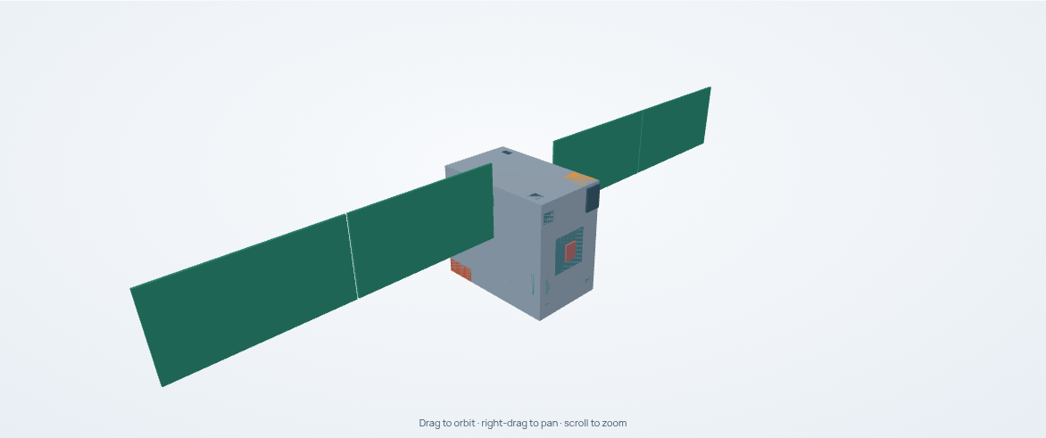
EX14: inspect the CAD assembly and watch its deployment.
Read each guide in two passes: follow the setup and outcome first, then trace assessment states, diagnostics and engineering quantities. Explore a completed study shows the Console's analysis views, tables, issues, scoring and agents. Use Compare designs when you change an assumption and run a new candidate.
These are illustrative concept studies, not reconstructions or independent validation of flown missions. Real-mission cases are planned separately and do not yet have runnable, validated reconstructions.
If a budget and a status appear to disagree, follow Interpret a result. For recurring terms and unit conventions, keep the glossary nearby.
What these examples establish
A normal starter must finish, retain complete required hardware, place all required items and provide a complete engineering evaluation. With CAD enabled, its exported parts must match recorded geometry and avoid represented material penetration. EX05/EX12 deliberately fails only the launch-width eligibility check; EX13 changes one envelope dimension to demonstrate the repair.
These are concept studies, not independently calibrated spacecraft designs. The bus outer shape is an envelope. Explicit decks are 19.05 mm conceptual sandwich material; harness cutouts are shared by placement and CAD, while mass uses gross deck area. Equipment occupancy counts proxies, not cables, connectors, access envelopes and every real integration feature. A low occupancy percentage is not a literal empty-volume estimate.
The compact/microsatellite/topology studies use a representative 75° beta angle; the larger-payload case uses 60°. Their momentum-unloading allocation is 3,600 s per 5,400 s interval. These cases do not establish all-season energy or ADCS performance. Reference catalog limits can leave conservative hardware choices, such as the compact example's battery and PCDU. Mass realism and supplier mechanism qualification require separate evidence.
EX06 leaves CAD off for speed. EX15 demonstrates a 42 handoff; a live controller validation needs a configured 42 runtime. Historical run bundles remain as recorded: reopen a new run to assess the corrected geometry.