EX14 · Symmetric deployable arrays
Examples index · Console starter catalog
Run this example
- Open Configure → Load Example. Choose EX14 · Symmetric deployable arrays.
- Name the project and run. Keep the starter inputs unchanged for your first run.
- Study → Generate CAD is Enabled by default. The server needs a compatible FreeCAD runtime for CAD export; native sizing can run without it.
- Validate the inputs, run the study, and follow the active stage in the run monitor.
- Open the completed run and inspect the results described below.
Use access and setup if you need a compatible runtime. First Console run illustrates the common loading, validation and execution steps.
Study and results
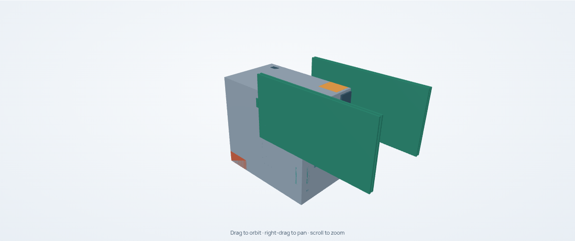
The radiator is restricted to the ±X faces so it clears the ±Y wing attachments and deployment paths. Explicit internal decks leave 0.641 m central clearance for the 0.6 m reference actuator. These are conceptual mounting and packaging choices, not detailed mechanism or structural qualification.
The starter explicitly selects four microsatellite reaction wheels and the BST BAT110 battery. These choices close the modeled attitude and electrical loads within the existing array attachments. The mission, payload, array mount limits and propulsion allocation are unchanged. The previous implicit hardware selections remain a negative regression case.
Choose EX14 · Symmetric deployable arrays: a 30 kg payload with 180/260 W demand, a 277 m/s chemical-propulsion allocation, stowed/deployed checks and explicit solar-facing orientation at 0° beta angle. Inspect the assembly and recorded motion below, then review the deployment checks and Evaluation together.
Inspect a deployable spacecraft
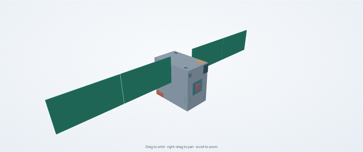
The EX14 · Symmetric deployable arrays starter produces two articulated, two-panel wings around a central bus. These images and the recording come from the October 25 reference run with CAD export enabled, before the explicit battery and wheel update. They illustrate the assembly and replay controls; current equipment placement and array sizing can differ.
Watch the recorded deployment
The recorded path passed its sampled geometric checks. Playback shows those poses at their recorded times; it is not a deployment dynamics simulation or a prediction of hinge loads. The geometry guide explains what the path checks establish. The views above remain available without playing or downloading the video.
Inspect your current result
- In Configure, select Load Example, then EX14 · Symmetric deployable arrays.
- Under Study, Generate CAD is already Enabled. CAD export needs a compatible FreeCAD runtime configured on the machine running Sindri; follow access and setup for the available runtime route.
- Name the run, validate the inputs, and run it. Leave the other starter inputs unchanged to run the maintained starter.
- Open Spacecraft → CAD Inspector. Select Stowed or Deployed, use Isometric, and scroll over the model to zoom. Drag to orbit and right-drag to pan.
- Select Play below the model, or move the Recorded sample slider. The stage buttons jump to recorded stages; the speed control changes playback speed without recalculating the trajectory.
- To inspect the interior, enable Transparent shell. Use each panel's visibility control in the parts list to reveal equipment behind it. Select a part to inspect its properties.

The same assembly with a transparent shell and the four solar-panel leaves hidden. Visibility controls change the view; they do not remove hardware from the design or its budgets.
Review Evaluation and the system assessments alongside the geometry. A CAD export and a cleared sampled path do not by themselves establish a feasible or qualified spacecraft.